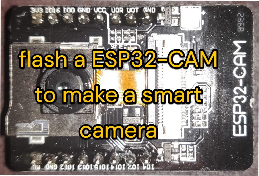
flash a ESP32-CAM to make a smart camera
Costing less than £10 or $10, the ESP32-CAM board comes equipped with WiFi, a camera and a micro SD-card slot. It needs a little work to turn this ‘development board’ into a something you can use to keep an eye on your desk, your pet or whatever. This is a fun DIY project to learn how to make a home automation accessory that you can monitor with Home Assistant. It takes time, involves hiccups so if you want a cheap security camera just buy one – it’ll come with an app which has fewer hiccups. (See if EZVIZ and WANSVIEW cameras suit your need).
a tutorial sequence: > the offer > why a platform > home assistant > ESPhome > camera project > main menu
what you need
- ESP32-CAM development board – comes with a camera. Some kits have an external aerial that I’ve never needed.
- Wire – if you use Dupont female to female jumper leads these will fit on the board’s pins. If the board has holes instead of pins you’ll instead solder male to female jumper leads.
- FTDI UART board – switchable 3.3v or 5v – plus a USB cable (you might need the older mini-USB cable)
- If you prefer to have a standalone web camera see my other project guide here instead. Do this to get to a result sooner.
- If you want to integrate the camera into Home Assistant you’ll need Home Assistant set up on a Raspberry Pi with the ESPHome add-on installed. The tutorial sequence above (home assistant > ESPhome etc) takes you through what to do first).
- you want a near-professional DIY monitoring system see my big Frigate project here.
what is ESPHome?
ESPhome is software that connects a ESP development board to Home Assistant. I use this a lot because sometimes I can’t buy the smart home sensor (or camera) I need at a good price. ESPHome allows me to make and monitor my home-made devices with ‘Home Assistant’*
*A camera project using an ESP32-CAM was my first foray into DIY home automation. It wasn’t the easiest but it was the most fun I think. I later did more challenging projects – I took apart and flashed Sonoff devices (although in 2022 this proved unnecessary). A next but easier task was to find a way to display readings of the Xiaomi temperature sensors that I’d placed in different rooms. Today I know how to buy a sensor and wire it to an ES32 board. I monitor how much heating oil is in my tank and how I made a smart meter that could tell me how much electricity I’m using through the day.
ESPhome will add your program to an ESP32 or ESP8266 board. This process is called “flashing a chip with firmware”. ESP chips are at the core of many automated devices from commercial smart plugs to home made projects. The EspHome software lets us choose what we want our device to do (eg a camera transmitting over wifi) and integrate these features to Home Assistant running on a Raspberry Pi. The instructions below show how to make the firmware and install it on an ESP32-CAM camera board.

compile the ESPhome code into firmware
What we’re trying to do is to add ‘code’ to the ESP chip and replace what’s currently there. Copy and paste this code into the ESPhome interface and add your wifi password and network settings. The code adds a wifi signal meter for the helluvit. We can re-edit this code for future projects.
# ITEMS IN BOLD NEED EDITING
substitutions:
   devicename: cat_camera

esphome:
   name: ${devicename}
   platform: ESP32
   board: esp32dev

#Enable logging
 logger:

# Enable a connection to the Home Assistant API
api:
  password: "YOUR Home ASSISTANT API password"

ota:
  password: ""

wifi:
   ssid: "YOUR_SSID"
   password: "YOUR WIFI PASSWORD"
   manual_ip:
     # Set this to the IP you want for the ESP
     static_ip: 192.168.1.171
     # Set this to the IP address of the router. Often ends with .1
     gateway: 192.168.1.1
     # The subnet of the network. 255.255.255.0 works for most homes

#Author by airijia.com board: esp32dev
esp32_camera:
   external_clock:
     pin: GPIO0
     frequency: 20MHz
   i2c_pins:
     sda: GPIO26
     scl: GPIO27
   data_pins: [GPIO5, GPIO18, GPIO19, GPIO21, GPIO36, GPIO39, GPIO34, GPIO35]
   vsync_pin: GPIO25
   href_pin: GPIO23
   pixel_clock_pin: GPIO22
   power_down_pin: GPIO32
   name: ${devicename} cam
   resolution: 800x600

 # Flashlight CHECK PIN
 output:
   - platform: gpio
     pin: GPIO4
     id: gpio_4

light:
  - platform: binary
    output: gpio_4
    name: ${devicename} light

# The following can be omitted
  - platform: restart
    name: ${devicename} restart

sensor:
  - platform: wifi_signal
    name: ${devicename} wifi signal
    update_interval: 600s

  - platform: uptime
    name: ${devicename} uptime
how to ‘flash’ or put this code into a ESP32-CAM – words and video
Inconveniently, the ESP32-CAM doesn’t have a USB socket to connect it directly to your computer. To work round this a FTDI module is required.

- Identify the VCC (or 3.3v input), GND, TX and RX on the ESP32-CAM
- Use female-to-female Dupont jumper leads to connect the ESP32-CAM to a FTDI UART board set at 3.3v.
- Add the code above to the ESPhome new device. Validate and compile the code into a binary file on your PC.
- Connect GPIO0 to GND with a Dupont lead as you plug the FTDI into a USB socket on your computer. You might also need to press the button on the ESP32-CAM.
- Use Esphome-flasher to upload the binary file to the ESP32-CAM.
- Follow the video hereon.
Compiling failed on the first word of the first line of the example code; Substititions.
Tardy reply from me: by now I hope you’ll have noticed that the compiler isn’t helpful at locating a problem – it gets thrown by as little as a wrong space or colon. It’s not the “substitutions:” bit, it’s further below.
A possible problem is that any of the sections further down your code is incomplete or incorrect.