use GitHub and Arduino IDE to create an ESP32 web camera
If you want to use a GitHub project with Arduino software follow this step-by-step guide. We’ll make an ESP32 camera web server using the Github code from ‘easytarget’.
An ESP32-CAM module consists of a 2MP camera (1622×1200), a flashlight, SD card slot and wifi capability in a matchbook-size package. It costs £6 posted from China or £8 posted locally. You could buy a ready-made, just as good IP camera for £25. However the DIY approach below offers clues into using many awesome projects on GitHub. Here’s what you need:
- An ESP32-CAM eg AI-THINKER or clone or WROVER
- Dupont wires (female to female), a FTDI Serial Adapter (about £3) and mini USB cable
- Arduino IDE software
- Owen Carter’s (aka “easytarget”) expanded web server project on GitHub
- USB cable to create a 5v power lead. (Older cables have fatter leads inside).
how we’ll make a web camera from an ESP32-CAM
Arduino IDE is used to compile firmware (our program) from a GitHub project. The Arduino IDE uploads this program to a ESP32-CAM. We power the ESP32-CAM, let it connect to the home wifi as we go to http://ipaddress in a browser to see the camera image.
All credit and thanks to the project’s authors*. I hope my write-up helps you avoid the many pitfalls.
i) set up the Arduino IDE
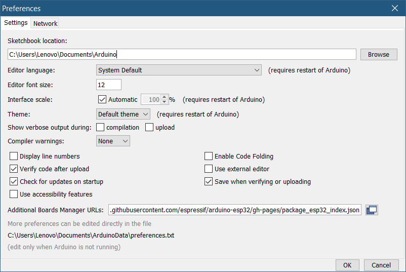
- Install and run the Arduino IDE software on your PC or Mac. Next go to Preferences to add ESP32 support to the Arduino ID: find the Additional Board Manager URL field and add the link below. If there are other links in the field add a comma followed by this link without a line break or space:
https://raw.githubusercontent.com/espressif/arduino-esp32/gh-pages/package_esp32_index.json
2) Go to Tools > Board menu > Boards Manager. Enter esp32 into the search box and click install on the Espressif entry.
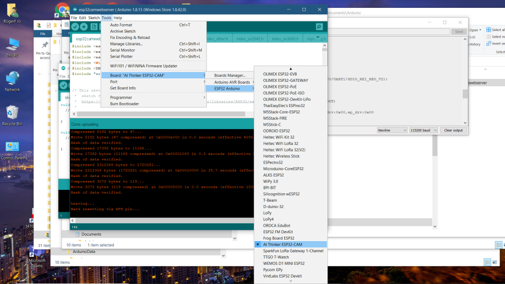
3) Go to Tools > Board menu and choose ESP32 AI-THINKER. Restart Arduino IDE if you can’t find it. Notice the Port option which you’ll later set to the correct COMx
ii) prepare the software from a Github project
- *Go to this project https://github.com/easytarget/esp32-cam-webserver. Look for the green Code download button and choose Download zip.
- Important I’m told: unzip the download and remove punctuation from the name. Below you’ll see I renamed the unzipped folder as esp32camwebserver and also renamed the .ino file as esp32camwebserver.ino
- Drag the renamed GitHub project folder into Documents/Arduino (or where ever your Arduino Sketchbooks reside)

4. Open myconfig.sample.h in a text editor (Notepad or Textedit). Immediately save this as myconfig.h ensuring that you’re saving it as a plain file.
5. Edit myconfig.h to suit your home wifi. You can see the (optional) edits I made below. Save myconfig.h

/* THE MINIMUM EDITS FOR 'myconfig.h'
// YOUR HOME WIFI DETAILS
struct station stationList[] = {{"secure_ssid","password", true}};

// DON'T UNCOMMENT URL_HOSTNAME BELOW UNTIL YOU'RE SURE IT WORKS
#define HOSTNAME "esp32"
// #define URL_HOSTNAME "esp32"

// ACCESS POINT SECTION
#define WIFI_AP_ENABLE

// MY ESP32CAM IS AN AI_THINKER CLONE SO NO CHANGES ARE NEEDED BELOW
#define CAMERA_MODEL_AI_THINKER
 // #define CAMERA_MODEL_WROVER_KIT
 // #define CAMERA_MODEL_ESP_EYE
 // #define CAMERA_MODEL_M5STACK_PSRAM
 // #define CAMERA_MODEL_M5STACK_V2_PSRAM
 // #define CAMERA_MODEL_M5STACK_WIDE
 // #define CAMERA_MODEL_M5STACK_ESP32CAM
 // #define CAMERA_MODEL_TTGO_T_JOURNAL
6. In Arduino IDE go to file > open > browse to the project folder inside the Arduino folder. Open esp32camwebserver.ino. Don’t edit this at all. Click the tick to verify that your coding is good to upload.
iii) compile the firmware, upload to ESP32-cam
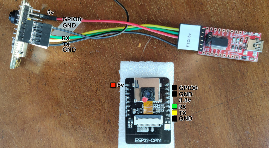
- The ESP32-cam has no USB interface so we use a FTDI serial adaptor to connect it to the computer to upload our firmware. You can fix Dupont connectors together to make this reliable (photo). This link to Adafruit FTDI Friend goes into detail on setting the voltage correctly. See that and this checklist:
- When you connect the wires also connect GPIO 0 to GND
- Connect the 5v from the FTDI to 5v and never to 3.3v or VCC.
- If a new COM port doesn’t appear when you plug this into the PC you need to install FTDI drivers (eg CH340).
- Set Arduino IDE > Tools > Port > COMx
2. It’s time to upload. The active Arduino window on screen should contain esp32camwebserver.ino. See the checklist below and then click the forward arrow. The code will be compiled into firmware and uploaded to the ESP. There are numerous things to go amiss but the worst is that you’d need to try again.
- Before you compile, set the board type to AI_THINKER and set the COM port of the FTDI
- Make sure that myconfig.h is a plain text file.
- In Arduino > open the Serial Monitor > set the Baud rate to 115000 else it’ll show garbage.
- Wire GPIO 0 to GND or press the EN (enable) button on the ESP32-CAM. (Or rarely: BOOT+release ENable) The serial monitor should read ‘Waiting for download’.
- Read hopefully positive messages below the esp32camwebserver.ino window.
3. With the software now firmly on the ESP32-CAM you can remove the GPIO 0 to GND lead and 5v live lead. Let the chip boot by replacing the 5v lead. Within a minute your ESP32-CAM should appear on your network. The Serial monitor will show useful messages including the IP address of the camera server. Open a browser window and enter http://the_ipadddress.
Rui Santos at Randomnerd and his helpful video below use the original web camera software. However see the end where he tries out ‘face recognition’ – a feature I haven’t found a need for.
4. When the camera webserver is working ok, you might experiment with the myconfig.h configuration file. You can use the unit in AP or access point mode: when the camera fails to find your home wifi it creates an access point and ssid you can connect directly to with your phone. Open your browser to see the camera and its controls.
5. Finally take an old USB 1 cable and cut off the smaller plug. Strip the red and black wires inside. Solder the red and black wires, with some heat shrink, to red and black Dupont plugs. Use female ends to power the ESP on its corner 5v and GND pins.
So….would this work with Zoom/MS Teams/Google Meet?
This controller would work in any application that listens for key presses including Zoom MS Teams and Google Meet.
So you’d be able to set it up as a Zoom/Skype/Teams/Google Meet webcam then? The reason I’m interested in this rather than just using a standard off-the-shelf webcam is that I don’t like having that blob on the top of my monitor. I want something that will pop up and down when it’s turned on/off. That way, the webcam will hide itself when not being used.
No I’m afraid you need to use a directly connected so-called webcam for telecoms apps like Zoom. There are many so you ought to be able to find a mounting design that suits. Eg a camera on a swing in desk boom arm is an alternative – I myself prefer this though it’s untidy. My project write up is for a security camera to access with a browser. The camera in this project is connected to the network, not the computer – it uses an IP address hence it is confusingly (but correctly this time) also called a web camera.