get water from a borehole – the electrics and control bit
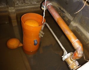
Remote homes and farms can get their water from a borehole – years ago the owner of my house drilled the garden until they found a water source. Today I see a manhole cover and below that is the borehole lined with a 6 inch plastic pipe. Inside that pipe hangs a pump (see pics) that supplies water to a house tank. It uses a trivial amount of electricity and no money is due to a water company. We test the water regularly. Occasionally, something goes awry but the fix is easy if you know how it’s put together. This post explains how a borehole is put together with my tips for simple but smart enough borehole monitoring and control.
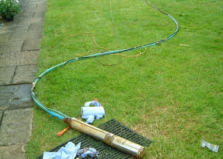
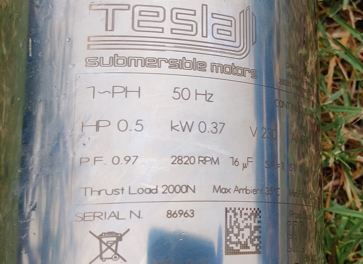
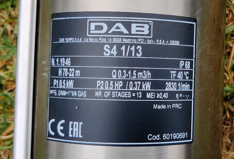
the borehole pump
A borehole pump is bought in two parts – a pump and a motor – and these fill the width of a pipe going down 10 metres to the water table. The pump connects to a 32mm MDPE blue pipe and the motor connects to a four-core electrical cable and all this weight hangs off a nylon rope that can be used to haul it out. An electrical connection down a well would be worrisome but the connection is resin-embedded and most unlikely to fail. The rest of this page is about controlling the pump – if you’re interested in the plumbing see my post here.
the electrics
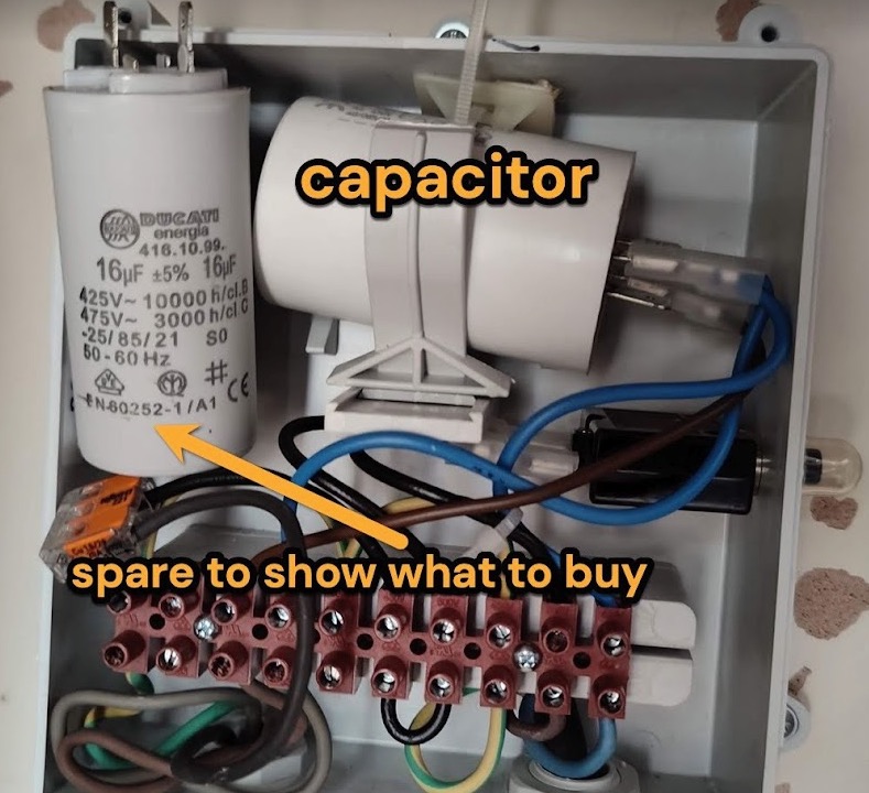
This box (pic) inside the house gets its power from a mains board 16 amp circuit breaker. If this were a toy motor you would connect plus and minus electricity wires to the borehole pump motor and it would turn and pump. However this mains motor (eg 230v) must be wired via a capacitor which acts like a starter motor in a car engine. When powered the starter capacitor charges and sends a burst of energy to turn the motor. Once the motor turns the capacitor circuit disconnects and the motor turns as motors do. There are no electronics in this box but even so, if your box is out of doors do relocate it. Tip: it costs <£10 to keep a spare capacitor. If the motor isn’t pumping yet power is getting to it, the capacitor is often blamed for not starting the motor. Over twenty years the capacitor has never actually been the cause of a problem but still I’ve changed it to prove that the problem was elsewhere.
starting and stopping the water pump as needed
To replace what we use as bathwater, for flushing and washing machines this household needs the pump to work for about 20 minutes a day. Clearly we need a way to tell the pump to stop and start and that’s done with a floating ball valve as in most houses. When the water tank level falls a floating ball drops and a valve opens to admit water into a tank. The floating ball then rises, closes the valve and no longer admits water*. Between the pump and the tank is a pressure sensor / switch which detects when the pump is working against a closed valve and then shuts off the power to the pump. When the tank level falls the floating ball valve opens, the pressure switch detects a pressure drop and energises the pump.
My worry-point is that I don’t want the pump to work against a closed valve nor do I want the pump to work if there’s no water to pump. The pressure switch electronics reliably guard against both these cases – furthermore if this pressure switch fails it not longer allows power to reach the pump.
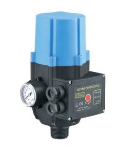


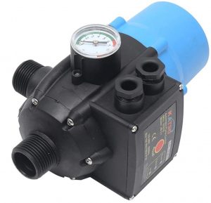
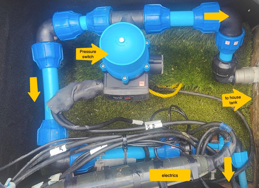
the pressure switch and its replaceable electronic circuit board
The lower 1 inch BSP connector of the pressure switch (photo) goes to a 32mm MDPE pipe going down the borehole to the pump. The side 1 inch BSP connector goes to a house water tank. A branch off this goes to a garden hose tap. There’s a mains supply wire and a wire going down to the motor (via the capacitor / box above). A ‘torpedo’ connector ensures that the mains electrics are safe. Ideally the pressure switch device shouldn’t be outside in the cold manhole where its electronics can suffer from condensation. However behind the four screws of the pressure switch are some electronics including a reed switch. (The reed switch reacts to a magnet that moves as the water flow changes).
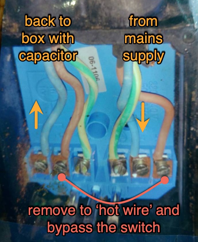
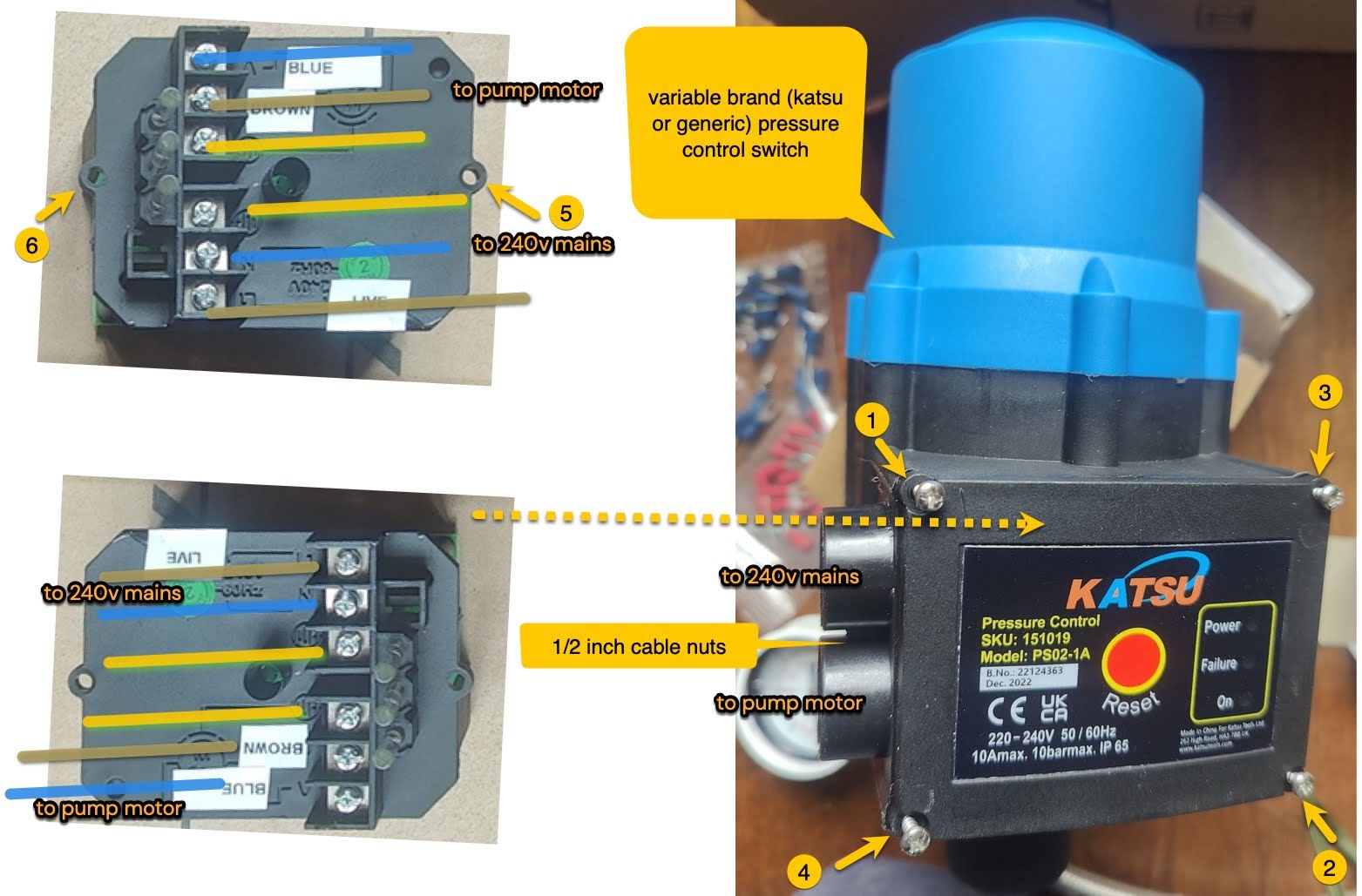
The electronics of the pressure switch (Coelbo Controlmatic / Katsu brand), being outdoors, are a potential point of failure. Whenever this failed I would ‘hot wire’ across the pressure switch to power the pump. (The pressure switch stops power getting to the pump). AT THE SAME TIME, I would open the garden hose tap such that when my tanks were full the pump wouldn’t pump to a closed system – the open garden tap was my relief valve. BTW by ‘hot wire’ I mean connect the pressure switch incoming live to the motor switched live inside the unit – see picture above.
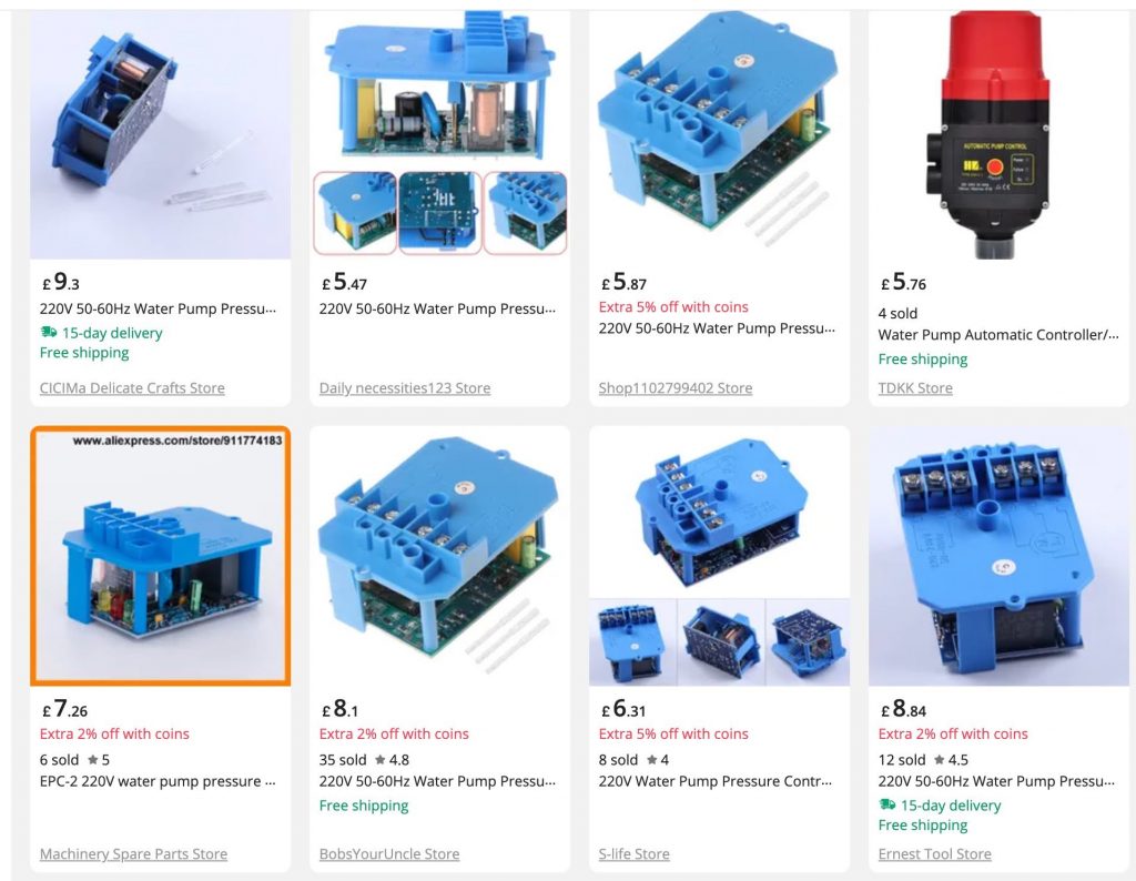
However I discovered that the electronics behind the pressure switch cover could be replaced when they got wet and failed me. In the past I would buy a whole new pressure switch unit just to replace a circuit board. Later I found a source of replacement circuit boards on Aliexpress. Later still I found that Kafuter K705 silicone could be used to (partly) encapsulate the circuit board and make it less susceptible to water damage. See photos.

avoid trickle filling your tank
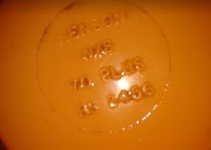
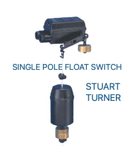
If this were all we’d have a nice simple system but in the early days I noticed that my pump was working every time water was drawn from the tank. There are special valves that allow a tank to drain down a bit before they refill. As well as guard against the pump overworking, the valves also ensure the water changes more often. The Henson type below I can no longer source but it’s simple and mechanical. The Stuart Turner float switch is an electrical version of the same thing. As well as solve a problem, the valves are a source of a new problem if they get stuck.
control and monitor your pump
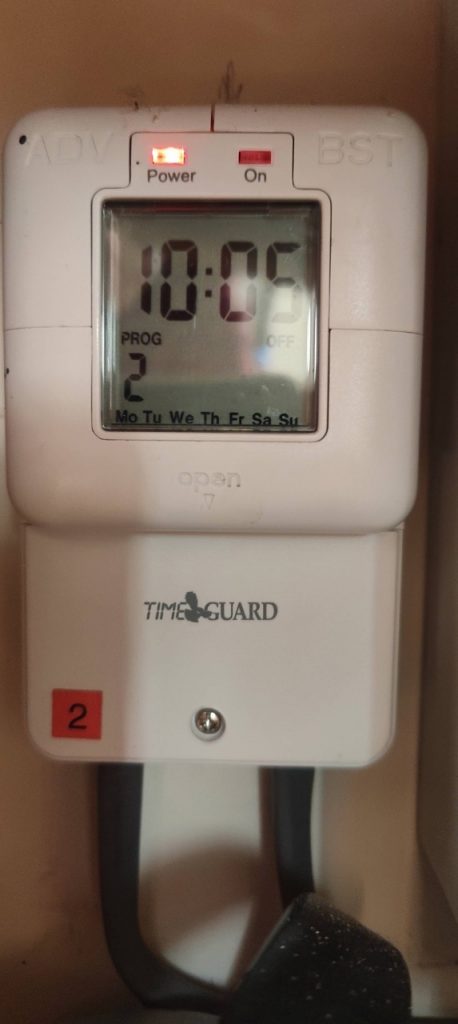
You don’t have to spend a lot to make the system ‘smart’. The power that runs to the switch box / capacitor above comes from the mains so I’ve fitted timers to this mains supply.
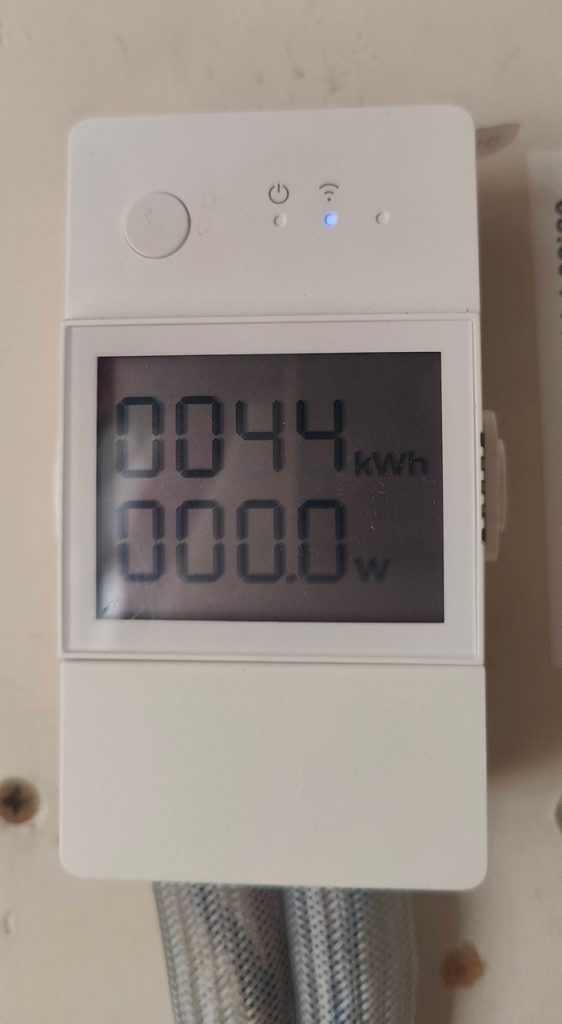
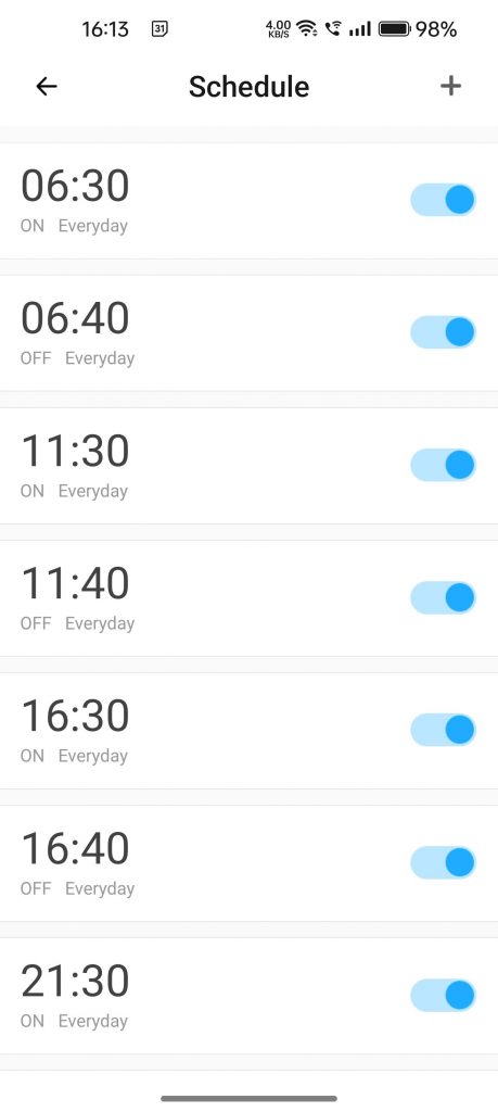
One timer is a Timeguard Immersion heater timer which is set to power the pump four times a day for 10 minutes each time. However this is presently not set because the other timer is the one in use: it’s a SONOFF POW Elite Smart power switch which powers the pump four times a day for 10 minutes. The Timeguard is a backup. I tee-off a pipe to feed the garden hose – I press the button on the Sonoff Elite whenever I need water at the garden hose. The Sonoff Elite can be set to turn off after an hour in case I forget about it. This settting is called ‘inching’.
Use Home Assistant to monitor and control a borehole pump
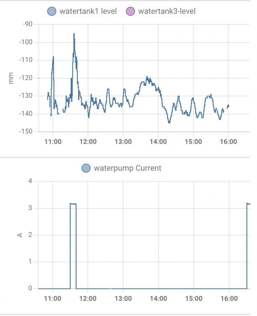
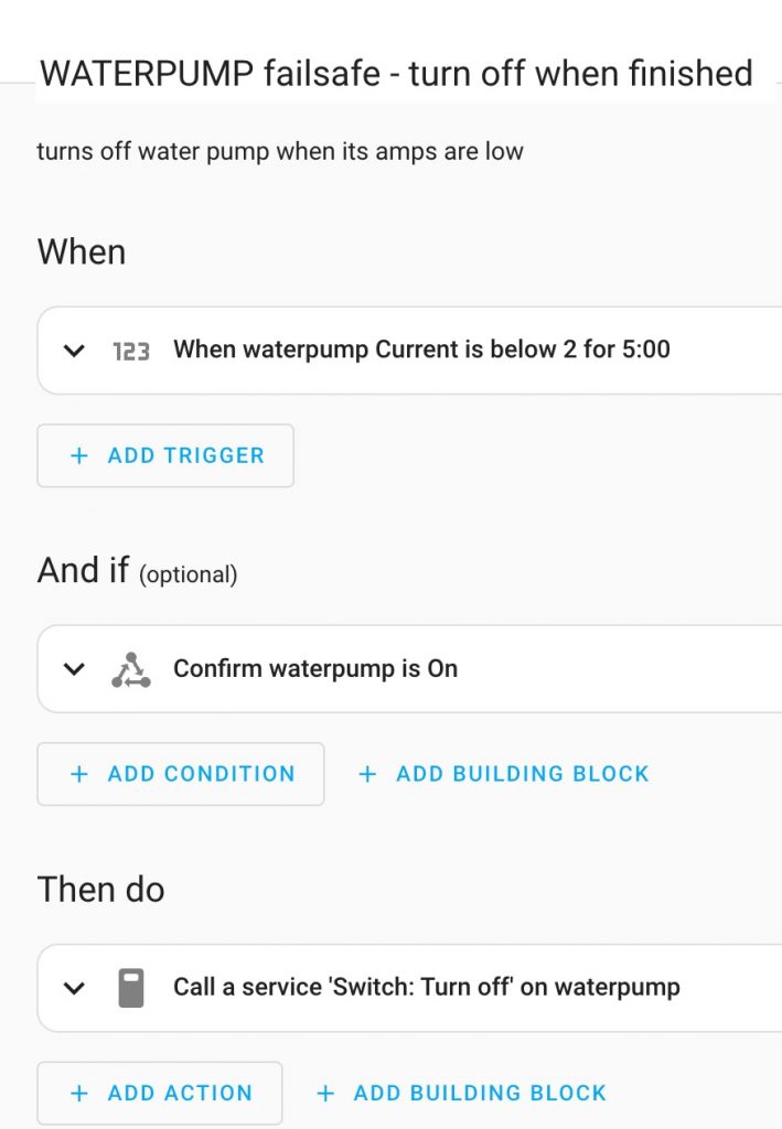
The Sonoff app shows me exactly when the pressure switch cuts in. It shows the amps used. I connect the Sonoff to Home Assistant. I created an automation to cut the power to the pump whenever the pressure switch has cut the power. Thus the system isn’t energised unnecessarily. The water tank level is monitored by a time-of-flight sensor (in this project)