set up rflink to respond to 433MHz devices and then integrate them with Home Assistant
a project to integrate inexpensive 433MHz RF devices with modern smart devices. We’ve brought all the instructions to get going with RFlink on one page.
see also: 433MHz smarter letterbox
how to set up RFlink so that it will read your RF sensors
The easiest ready-to-go device to integrate 433MHz RF devices with smart home kit is the Sonoff RF Bridge. For example, I used it to sense when my door contact sensor reacts. I have 433MHz RF door bell buttons which I use to switch the room lights. And then there’s a water leak sensor which one day might alert me to a leaky pump. In all these cases a sensor transmits a wireless RF pulse which is picked up by a Sonoff RF Bridge. The bridge relays an MQTT message to Home Assistant. And then you can do anything. I have two bridges, the just mentioned one was installed with Tasmota, the other is straight out of the box. The unmodified one reacts to door contact sensors (eg my letterbox project), water sensors and motion sensors so this is the easier idea to start with.
But the examples above are lucky examples of compatibility. The Sonoff RF Bridge only responds to or controls some RF devices. You’d need to modify the Bridge (really hard) and install OpenMQTTGateway on it to give it more capability. (A lack of step-by-step instructions for OpenMQTTgateway left me for dead). Even if I’d used it I’d still find RF devices that the bridge didn’t respond to.
Luckily I stumbled upon RFlink – an alternative receiver / transmitter that is capable of recognising my Oregon Scientific, HomeEasy and Friedland RF devices and more. It even outputs RF to switch my HomeEasy sockets. My RFlink project took ages because the instructions are all over the place. So the rest of this page aims to put them in one place and take us forward. There’s a lot to do BUT two+ years later it has not needed attention and it has not failed me.
what you need to set up RFlink
- ideally a Raspberry Pi running Home Assistant although there’s enough below to get started with other technical automation hubs.
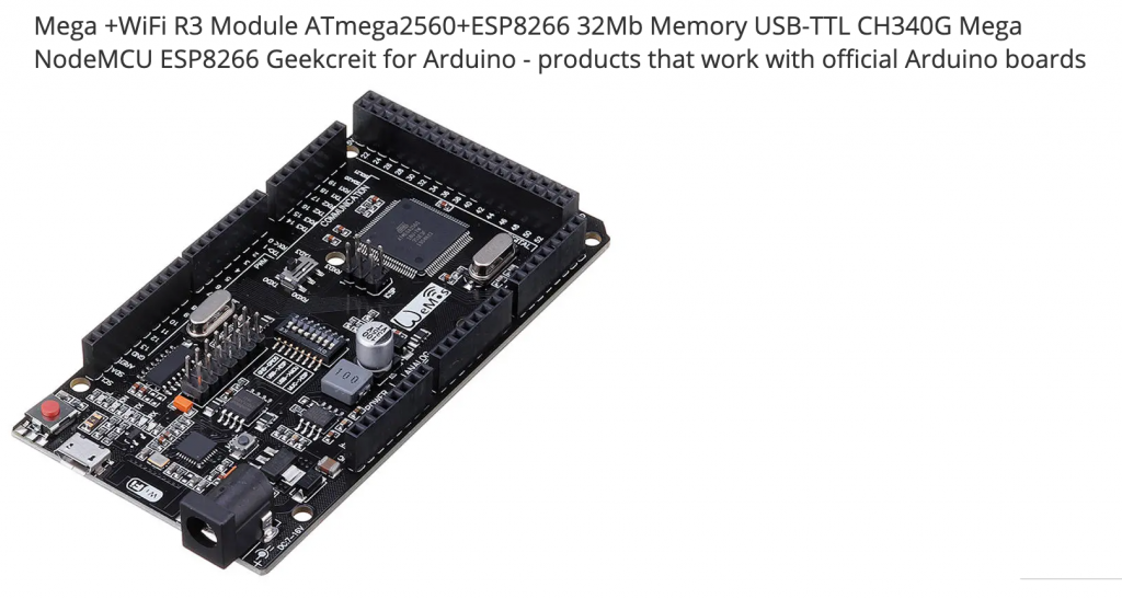
- an Arduino Mega R3 or clone (£10) to plug into the Raspberry Pi with a USB cable. I bought a clone Mega R3 from China. You just need an Arduino Mega R3 – anything else requires effort just to save a £1.
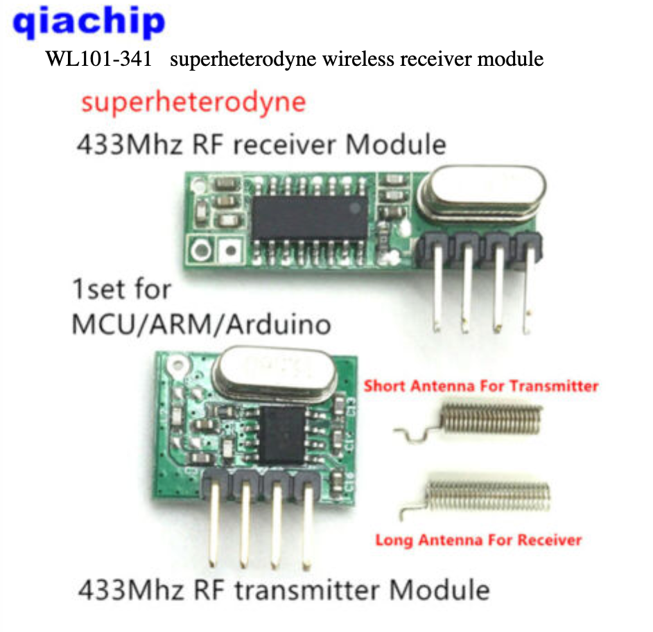
- an RF transmitter and RF receiver and some wires (as below = under £5). Or you can buy a kit from Nodo webshop
- a tiny bit of soldering skill to attach the aerials
- some 433MHz devices eg doorbell, button pushes, alarm, water, PIR sensors, HomeEasy stuff that you want to make use of
- the RFlink firmware / software to put on the Arduino via a Windows PC. You do this bit once only
leave the receiver for now, first install RFlink on the Arduino Mega R3 (in Windows)
Plug the Arduino Mega R3 into a Windows PC with a USB cable. Windows should install the necessary drivers for the CH340 and assign a COM port so that we can upload the software to the board. Sometimes the drivers need installing separately from wch.cn but a reboot may show this to be unnecessary.

Above: download the RFlink firmware/software for the Arduino. Open the zip and launch the RFlinkloader application. Below: when the application launches it should find the COM port.

Notice that the software has a button to scan the available ports, a drop-down to select a COM port and a button to select the firmware file (rflinkloader.cpp.hex). You might need to press one of the physical buttons on the Arduino to wake it up. The firmware file uploads and your Arduino should be ready to go. When you click Serial port Logging you’ll see some signs that the software is working. Disconnect the Arduino so that we can add the RF receiver kit.
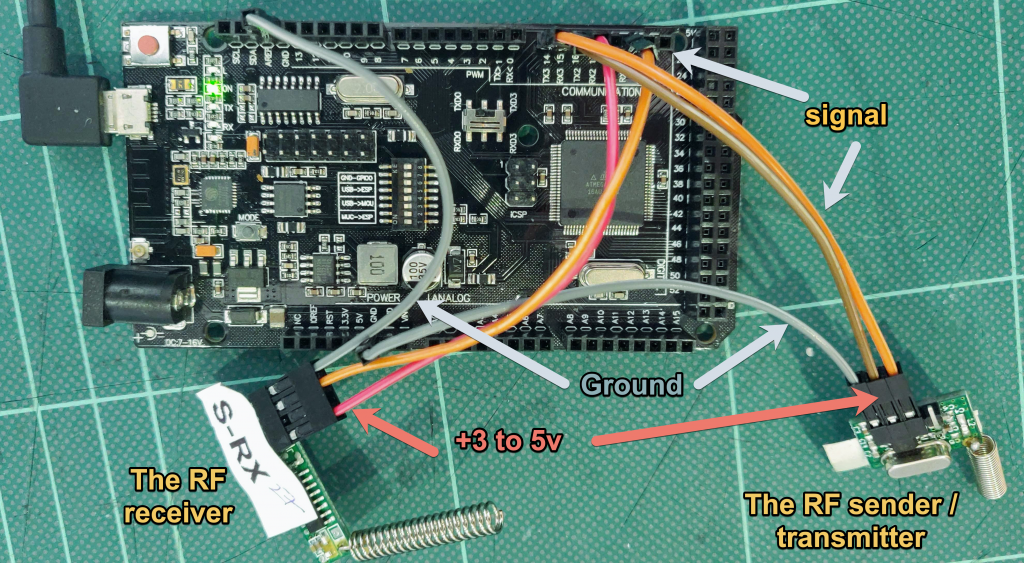
add the receiver and transmitter to the Arduino
You need six male-to-female Dupont wires, three for the RF transmitter and three for the RF receiver. Solder the correct aerial to the Antenna hole in each board. Connect them to the Arduino Mega as follows because the firmware is expecting to see things on the pins used here.
reconnect the Arduino to the Windows PC running RFlinkloader

With the Arduino and the RF kit connected to the PC click Serial port logging. Now send a signal from one of your RF devices and you ought see some output on the screen. Make a note of the device and what it’s recognised as. I’d recommend that you now power down everything RF to achieve radio silence. You can now identify the name and code of as much kit as you have. You can copy and paste the log text or write this on paper. The key to-do at this stage is to find out if RFlink senses your sensors. You will waste time later, changing batteries and so on, if a sensor appears dead because RFlink isn’t able to respond because say, the send frequency isn’t right. BTW if you want to use 866MHz sensors use the appropriate RF sensor / aerials.
If you find that some devices aren’t recognised, click Debug in the Rflinkloader window. You’ll at least find that they are working. I had the least success getting a response to piezo RF doorbells. I guess that the reason is to do with them being coded or tied to the receivers. You might contact the RFlink software maker about apparently dead sensors but first read how the protocol works here.
connect the Arduino to the Raspberry Pi running Home Assistant to get the USB port name
Click Supervisor > System > Hardware. If needed reboot the RPi to get the USB serial port. See the official docs

add some code to your Home Assistant configuration.yaml
The following code adds the RFlink integration and sets it to auto remember any RF signals it receives. Devices that are sensors (eg Oregon Scientific weather station) will be set as sensor entities. All other devices are understood as lights. Later on we’ll fix this and more. Right now, check your configuration and then reboot the Raspberry Pi.
# 433MHz feature
rflink:
# not this  port: /dev/ttyAMA0
  port: /dev/serial/by-id/usb-1a86_USB2.0-Serial-if00-port0
# this never worked port: /devices/platform/soc/fe201000.serial/tty/ttyAMA0
  reconnect_interval: 30


# this port is shown in the image above. your detail might be different
logger:
  default: error
# add the following to the existing logger section
  logs:
    rflink: debug
    homeassistant.components.rflink: debug

light:
# add the following to the existing light section
  - platform: rflink
    automatic_add: true

sensor:
# add the following to the existing sensor section
  - platform: rflink
    automatic_add: true
add the entities to your Home Assistant overview and automations
From now on Rflink will store the devices it discovers to Home Assistant. Home Assistant will create an entity for anything new. Of course you can display the state of the entities in the Overview / front page. However you must now do the work of identifying what sensor is what.

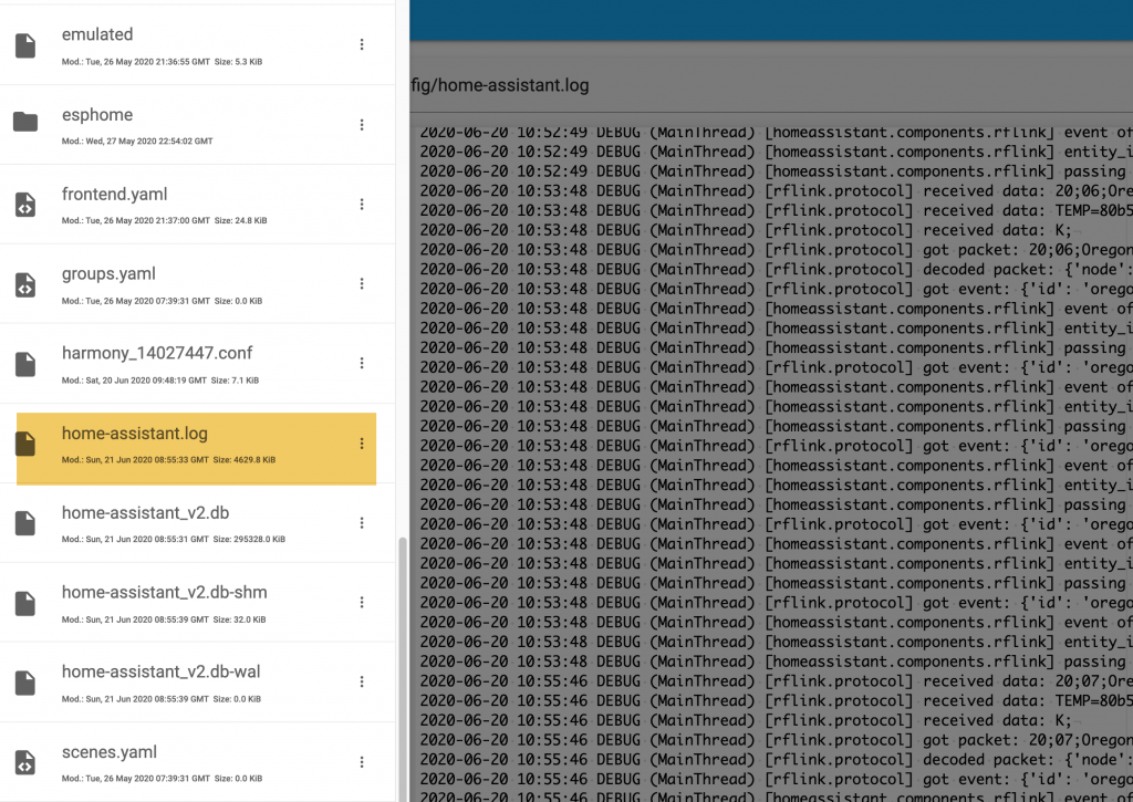
check the logs for probs
When the discovery above takes place Home Assistant keeps a log in the background. You can access this in the config folder – it might help you identify which device is which.
configure the light entities, write automations and scripts
When your switches (push switch; remote button) have all been identified (as lights) you can comment out the automatic_add line in your configuration.yaml. Your next step will be to re-configure the lights as switches. Notice the name “newkaku_004c899e_b” (below) which tells you the protocol, the code and the unit number needed to send the switch signal from Home Assistant to your device. I found that my things worked better when I added the switch detail – though it might not be essential.
automatic_add: false
switch:
 platform: rflink
 devices:
   newkaku_004c899e_b:
     name: heunit1 friendly name
You can now place the entities you found on the Overview of Home Assistant. You can also incorporate the entities into an automation that turns on a light when a button is pressed.
keep a record of your codes!
I now put a label on each item and keep a record of the device RF codes and so on in a Google spreadsheet. Some devices change their codes over time and this is infuriating. If you spot a pattern to the code change you can set up an alias list as shown for the back_PIR below. I’ve included some real working examples below to show how we finally integrate RF devices into Home Assistant. After a reboot devices such as those below will appear as Entities in Home Assistant.
#my binary_sensor section of configuration.yaml for RFlink

  - platform: rflink
    devices:
      back_PIR:
        name: back_PIR
        off_delay: 5
        aliases:
          - friedland_672caa6e_1
          - friedland_672caa6e_2


#my binary_sensor section of configuration.yaml for Tasmota Sonoff bridge

- platform: mqtt
    state_topic: "rfsignal/tele/RESULT"
    name: "walllightbutton"
    value_template: '{{value_json.RfReceived.Data}}'
    payload_on: "EFCA61"
    payload_off: "EFCA61off"
    device_class: power
    # device: black round tabletop button
    qos: 1
    off_delay: 3
#my switch section of configuration.yaml
switch:
switch:
  - platform: rflink
    devices:
      newkaku_004c899e_b:
        name: heunit1
      newkaku_004c899e_b:
        name: heunit1
      newkaku_004c899e_c:
        name: hesocket3
      newkaku_00072d3e_c:
        name: hewhite7
      newkaku_014cae6c_3:
        name: hesocket1
      newkaku_004d7f26_b:
        name: hewhite9
      newkaku_014cae6c_1:
        name: bedroomlight2
      newkaku_014cae6c_9:
        name: bedroomlight1
      newkaku_0002cb32_b:
        name: pondlights
Hi Roger,
Thanks very much, great write-up.
Do you know whether the same/similar process will work with 868MHz devices? I know there’s an 868MHz version of the RF kits.
Thanks,
Miranda
Hi, thanks for your question. Your first requirement is less about the frequency, it is that your devices are named on the list of compatible RF devices. For example many RF buttons and sockets work with RF Link and there are unexpected finds. Several doorbell buttons of mine didn’t work (possibly because they have some secure code to stop them working with the neighbour’s). So do that first. You might find OpenMQTTgaterway claims compatibility with your brand.
Yes I’d say you were in with a very good chance of using 868MHz devices. Yes, the Nodo shop suggests it is indeed a case of using another transmitter/receiver pair for that frequency. Ebay sell modules too. What you read on this page took research and luck. Good luck
http://www.rflink.nl/blog2/wiring
Is it possible to use the Mega+wifi R3 onboard WIFI instead of the USB serial
According to this doc Home Assistant can listen over TCP so a likely yes, https://www.home-assistant.io/integrations/rflink/
I wanted to do this, to locate my RFlink somewhere central, but I found the RF signals to be quite good.
Still I’d encourage you to explore your wish.
While I do own similar kit I have still to understand how to send serial data from the Arduino > wifi.
Thanks for getting me up and running!
That’s encouraging to know Kim. Thanks for dropping by.
My turn to start dealing with RFlink ! I should have tonight the Arduino card and at least the RF receiver.
I will try to get few sensors recognized in HA !
Best wishes!
I’ve finished the setup.
I’m using a real antenna, and condensators top optimize the reception of RXB6, but still very very weak reception…
With a remote for switches, it’s working only once for 10 tries, and at less than 2 meters..
Any idea what could be wrong ?
Well done for getting this far but Oh dear.
I would have started with a regular receiver.
I have never been lucky with aerials of any kind … However the range of my 443MHz signals is at least 50m.
Best wishes.
Roger will any R3 mega work ?
I notice on your list “+wifi”
Do you have a link to the one you used or one in amazon
Cheers for your query. I appreciate the confusion Arduino caused by the name. My board has wifi but it’s not used.
You need an Arduino Mega R3 to run the software at https://www.rflink.nl/ The price of clones seem to be around £18
You don’t want ‘UNO’ in the title. I read somewhere that the ‘mega’ has more memory.
ORIGINAL https://store.arduino.cc/collections/boards#:~:text=Arduino%20Mega%202560%20Rev3
CLONE on Amazon ELEGOO Mega R3 Controller Board Compatible with Arduino IDE with USB Cable Blue Version
CLONE on aliexpress MEGA2560 MEGA 2560 R3 (ATmega2560-16AU CH340G) AVR USB Board Development Board MEGA2560 PRO For Arduino Expansion Board DIY Kit
CLONE that I bought was https://uk.banggood.com/Geekcreit-Mega-+WiFi-R3-Module-ATmega2560+ESP8266-32Mb-Memory-USB-TTL-CH340G-p-1205437.html?cur_warehouse=CN
Hi, thabks for this how to.
Do you know of a way to “put” the light and switches in specific rooms?
Now they are all collected under the “light” section of the homepage.
The entitys mis an unique_id so i cant figure iut how to organise them in rooms
Hi and cheers for flagging this. I looked for you but only found a many people finding the same missing feature. This link looked promising however… (I can’t check it myself just now)
https://community.home-assistant.io/t/moving-a-light-from-one-area-to-another/208360
Hi thanks for your replie.
I forgot to answer.
Ive tried every thing i found on the forums. Youre link was new to me but it didnt work.
Seems like the RFLink setup does not cover rooms (yet). Shame there isnt a workearound for it.
I want to keep the dashboard for my family simple and easy. So Ill look around for that. Maybe experimenting with different scenes and delete the “light” section from the dashboard
For the record:
The sensors/lights/switches we’ve set up manually here do not have a unique ID nor do they ‘belong’ to a device. Had they belonged to a device we could change their area (as per the link).
Hopefully someone knows where, at the back end the AREA (or ROOM) information is stored – and we could tweak that. Creative workarounds like your suggestion may well find a way.
I see the value you gain from using Rooms / Areas in your user focussed dashboard. I haven’t used Areas largely due to my laziness. Instead I use entity cards to do my organising. The entity card headings I have give the flavour: They are quick switches; living room, zoom studio lights; readings from the last hour, graphs from the last week, alerts (oil, water tank, letterbox open).
Hi, yes did something similar and it fits my needs perfectly.
I just created a new dashboard and inserted light entities.
In the dashboard you can rename the entities themselves if needed but also the “headline” of the incertet entities. So I named them after the rooms and inserted the right rflink lights and switches.
This is what I was searching for.
Shame it can’t work with the original dashboard but at least this is a way things are better organized
Cheers. Nice idea to rename entities for a room.
I just recalled that I title each automation eg ‘LIVING ROOM ….’ which also helps me a lot.
One tip I’ve not yet shared is that every entity I have is titled in lowercase. Lowercase is so much easier to read. My Rooms and Groups have a capital letter.
Hello,
Finally, I found the explanation I was looking for;
I have some switches and plugs from Chacon DiO. They should have worked with RFLink, but I couldn’t get them working.
Now they are working (from time to time) after a power shutdown they are disappeared in entities. Here some examples from the code I received from RFLink loader.
20;11;NewKaku;ID=0054f47e;SWITCH=1;CMD=OFF;
20;12;NewKaku;ID=0054f47e;SWITCH=1;CMD=ON;
Do the 20.11 – 20.12 before the code matter ?
I can make it work with Entities Card configuration but the ON button works as Toggle (That is not a problem, as long as it works.
When I try to put them in the switch section of configuration.yaml I get the following error.
* Invalid config for [switch.rflink]: expected a dictionary for dictionary value @ data[‘devices’]. Got None. (See ?, line ?). *
(Config.yaml)
light:
– platform: rflink
automatic_add: true
switch:
– platform: rflink
automatic_add: true
devices:
0054f47e_1:
name: Buro
I also don’t know when to exactly change the automatic_add: true or false.
Anyway, I very gratefull for the explanation, Its why I already came this far, after months of trying,
Fred Boliau
(apprentice Home assistant
Thank you for puzzling me Fred – it’s a while since I played with this. May I first recommend that you record your knowledge!
However:
1) I couldn’t myself pursue this as a solution but if the below idea fails do note that RFlink can learn codes and transmit them.
2) Newkaku coding is used by the HomeEasy switches and sockets that I have. My sample below shows the correct config for the log lines you see. The invalid error I’ll wager is to do with HA/indentation because you otherwise have it correct.
3) After some experience I’d agree that the response / behaviour is a bit iffy. HA might throw a complaint that it didn’t manage to switch and yet often it does.
4) I’ve assumed that 20;11 describes the direction (send receive) and was not relevant. But see this explained in the ‘protocol reference’ here https://www.rflink.nl/protref.php
5) I didn’t experience any toggles myself but a soln might be in Home Assistant. In Developer > Services I’d suggest to try calling each of the switch services. I’d then look at the docs for RFLink Switch and try eg fire_event etc to see if this changes the toggle behaviour.
In my log from Home Assistant.log I see this
2022-11-10 18:05:42.593 DEBUG (MainThread) [rflink.protocol] received data: 20;9E;NewKaku;ID=004c899e;SWITCH
2022-11-10 18:05:42.597 DEBUG (MainThread) [rflink.protocol] received data: =c;CMD=ON;
So I put in my Home Assistant configuration.yaml – but see the indents further below:
switch:- platform: rflink
devices:
newkaku_004c899e_c:
name: home-easyswitch
INDENTATION
switch:
2 spaces – platform: rflink
4 spaces devices:
6 spaces newkaku_004c899e_c:
8 spaces name: home-easyswitch
All best wishes
O K
Thanks,
I’ll try again Tomorrow.
Goodnight,
Fred
Hi,
It worked what a few spaces more ore less can do.
It is not 100% stable, sometimes switches need aliitle encouragement, a click or two.
See what we can learn next,
Many thanks again
Fred
OK that’s progress. I’ve been exercising my switches and this is where it is:
Years on and it still works.
As this is RF we can never be sure what on/off state a socket is in. If you want to surely turn on, assuming you’re not toggling by this, send more than one on. My sockets are turning on studio lighting – it’s not critical. (As I said somehow RFlink can learn and send codes and perhaps that’s a way forward)
I’ve had my value on the sensor side: door contact sensor, water detector, RF push button, oregon weather sensor, RF stick-on light switch.
Roger,
Tot aan:
rflink:
poort: /dev/serial/by-id/usb-1a86_USB2.0-Serial-if00-port0
# deze poort wordt weergegeven in de afbeelding hierboven. uw detail kan anders zijn
logger:
standaard: fout
# voeg het volgende toe aan de bestaande loggersectie
logboeken:
rflink: debuggen
homeassistant.components.rflink: debuggen
gaat alles goed, maar dan:
ik krijg
ttyACM0
/dev/serial/by-id/usb-Arduino__www.arduino.cc__0043_8563231303935110C092-if00
ttyAMA0
ttyUSB0
/dev/serial/by-id/usb-1a86_USB2.0-Serial-if00-port0
ttyUSB1
/dev/serial/by-id/usb-1a86_USB_Serial-if00-port0
geen van alle geeft an dat er verbinding is.
Doe ik iets fout, of vergeet ik iets?
Dick
I’VE TRANSLATED TO THIS AND I HOPE I’VE READ THIS OK:
roger,
re:
rflink:
port: /dev/serial/by-id/usb-1a86_USB2.0-Serial-if00-port0
# this port is shown in the image above. your detail may be different
logger:
default: ???
# add the following to the existing logger section
logs:
rflink: debug
homeassistant.components.rflink: debug
everything goes well, but then I get
ttyACM0
/dev/serial/by-id/usb-Arduino__www.arduino.cc__0043_8563231303935110C092-if00
ttyAMA0
ttyUSB0
/dev/serial/by-id/usb-1a86_USB2.0-Serial-if00-port0
ttyUSB1
/dev/serial/by-id/usb-1a86_USB_Serial-if00-port0
none of them indicate that there is a connection. Am I doing something wrong, or am I forgetting something?
Dick
REPLY:
I can’t be sure. BUT the config I used to use stopped working in 2023 so I’ve changed the port and it worked again. Try this on a Raspberry Pi4:
rflink:
port: /dev/ttyAMA0
Thanks Roger
I will try
Dick