automated fade up dimmer for analogue LED Strips – using a MOSFET and ESPhome
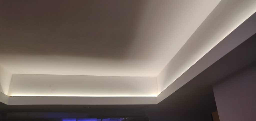
This ceiling ‘coffer’ is lit by four 5m LED strips – each is cut to fit the space. When my kitchen lights turn on they fade up in a few seconds and when they ‘off’ they fade down. While that’s actually unremarkable it’s a rare feature in anything you can buy at a fair price. At night the lights only fade up to 20% so as not to surprise someone just out of bed, grabbing a late snack. This project aims to make the lights fade up and fade out gently whenever motion triggers them.
In 2017, and still in 2023 if you want really, really bright white light, analogue white LED strips are the thing to get. At £8 for 5m at 150 LED/m and high lumens I could not complain. You could use digital, addressable and easily dimmable LED strips (eg WS2811) but at a few times the cost for a 5m strip anywhere this bright. I use a RCWL-0516 microwave motion detector and a ESP32 board. A Home Assistant automation ensures that they don’t turn on at night when that would surprise someone just out of bed, grabbing a late snack.
Surveying the dimmer market I found Lutron equipment but to my mind it was too expensive for so trivial a task as dimming. Then I found the analogue QUINLED board – but making one of these seems overwhelming. I also found an inline remote controlled dimmer (as cheap as £6 – below) with 5.5mm plug – but it doesn’t make the lights fade up when turned on. So I ended up using ESPHome in Home Assistant, an ESP32 can pulse the 12v supply to a LED strip and control its brightness via a MOSFET. A MOSFET does the dimming – it’s like a relay with a gradual on-off. And it works well as below.

finding a MOSFET that handles lots of current and is triggered by a tiny signal
I used an Arduino IRF520 Mosfet module for its convenient connections. This MOSFET can handle the 2a amps and 12 volts needed to light and dim one of the light strips. There are several things to note:
- this IRF520 MOSFET does indeed get warm. If I used this MOSFET I would need to bolt a heatsink to its metal tab.
- the light output during the fading and dimming is not linear. It’s not a big deal but the fade up appears to do nothing for a good while before we notice the light. A solution is to make the fade-up run faster (and/or make the last part of the fade up run slower).
- the IRF520 Mosfet isn’t really a logic level device. It needs more volts on the signal pin to fully open the MOSFET gate. In other words, the LED strip gets only 10v of the 12v available, and consequently it is slightly less bright. My solution was to solder in a logic level TO-220 (this is its physical size) MOSFET. I used a IRLb8721 30v 62a and can recommend that. An IRL520 was also suggested.
- as I have four LED strips in the ceiling I used a MOSFET board for each strip. A few years later I simplified this to two MOSFETs. I used 5.5mm male and female connectors for the LED strip and power supply – however I later made my own soldered connections using 18-AWG silicone coated copper wire. You may need a project box for the mess of wires.
- Do turn the 12v power off when making these connections as you can damage a MOSFET so that it no longer dims.
about these extra bright analogue LED lights
- The initially used LED light strips were branded LEDMO and they need a 2A 12V power adapter (that’s <24W per strip). Because I need four LED strips I bought one aluminium cased mains powered transformer that delivers 150W at 12V.
- Each strip has 600 x 2835 LED chips giving 2700K white. At 120 LEDs per metre we get possibly up to 9,000 lumens per 5 metres. Each strip cost GBP £15 in 2017 on Amazon. The total cost of the project was 4 x £15 + £40 power + £20 smart plug + £20 cables and connectors.
- By 2023 my LED strips were brown and shabby so I replaced them with ‘flexible COB’ LED strips from BTL on aliexpress. These are made of LEDs that are so tiny you don’t see the individual LEDs.
- The strips come with the 5.5mm x 2.1mm power sockets/plugs you’ll find on CCTV cameras, routers and LED strips. I bought a four to ‘one male to four female adapter’ to power the strips; some 17 AWG (1mm) silicone coated wire for the 12v supply. I might have bought LED strip end connectors and plugs however to be safer I solder my own plugs using silicone wires and use WAGO connectors.
- I notice no concerning brightness drop over 5 metres – although professionals would use 24v LEDs. Everything else can stay the same.
wire the the ESP32, power supply and the LED strip light
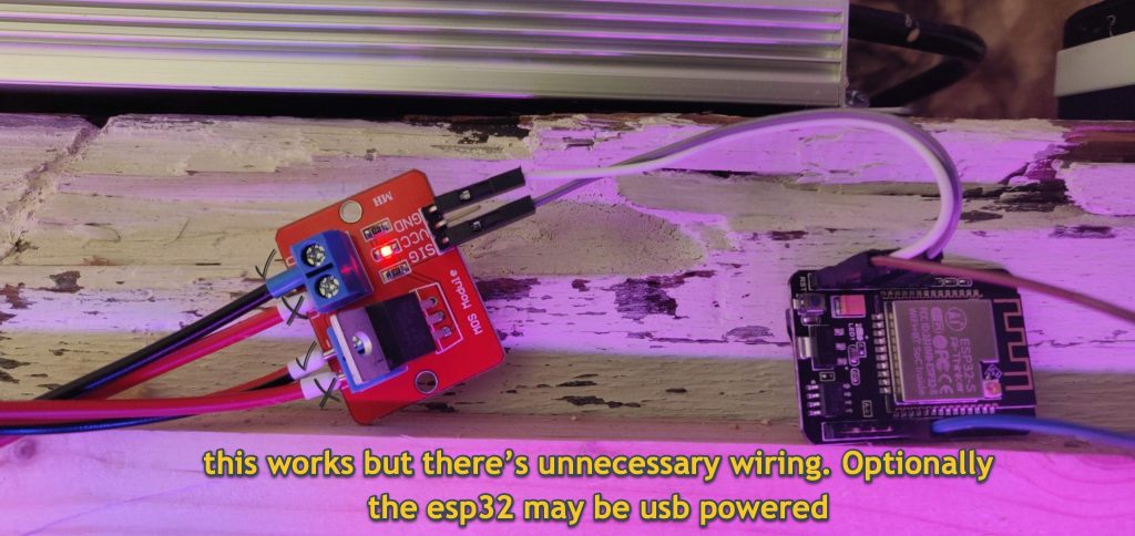
The MOSFET module saves some of the effort of wiring. One ESP32 has enough output pins to control all four LED strips via four MOSFETs. I considered the need for a heatsink on ther MOSFET if the light use exceeded 2a. Instead I soldered and swapped the built-in MOSFET for a ‘IRLb8721 30v 62a’. You could make the wiring more beefy (eg use 1mm copper).
go to ESPhome in Home Assistant, add a ‘new device’ and use this configuration
Go to the ESPHome section of Home Assistant and set up a new device (green button). Here you will tell the ESP32 what you want it to do and paste the lines of text below. You’ll add your wifi details, and the pin/s you connected to the MOSFET/s. The following code can replace the code in a newly created ESPhome device:
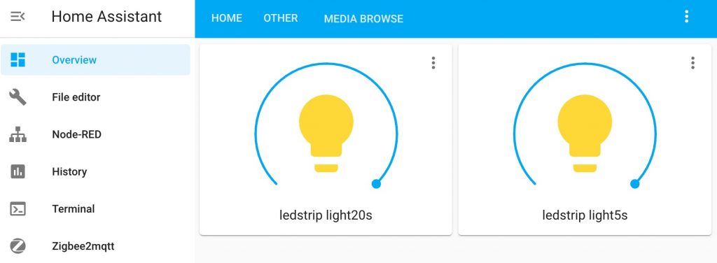
# Create a new node in ESPHome. Add these lines to the yaml file
substitutions:
   devicename: ledstrip
 esphome:
   name: ledstrip
   platform: ESP32
   board: esp32dev
 wifi:
   ssid: ""
   password: ""
   manual_ip:
     static_ip: 192.168.1.XX
     gateway: 192.168.1.1
     subnet: 255.255.255.0
 # Enable hotspot (captive portal) in case wifi connection fails
   ap:
     ssid: "ledstrip fallback hotspot"
     password: "password"
 captive_portal:
 logger:
 api:
 ota:
 # esphome will create two keys for the api and ota above

web_server:
   port: 80
# the web server is handy for testing but you can remove those two lines.

output:
 platform: ledc
 pin: GPIO27 # see below if you have more strips on one ESP32 board
 # frequency: 20000Hz # THIS LINE IS NOT NEEDED
 id: ledcout

light:
  - platform: monochromatic
    output: ledcout
    name: ${devicename} light20s
    default_transition_length: 20s

  - platform: monochromatic
    output: ledcout
    name: ${devicename} light5s
    default_transition_length: 5s

switch:
  - platform: restart
    name: ${devicename} restart
- Add and edit the code above using the Esphome editor.
- Install the code using ESPhome web or an app called ESPflasher. If the ESP32 board doesn’t have USB connect it via a 5v FTDI adapter to your PC with a USB lead.
- In ESPflasher, choose the COM port that appears, choose the binary file you just made and click Flash firmware.
- If nothing happens or the install fails view the logs. Try again after pressing one of the buttons on the ESP32 – when you see ‘waiting for download’ now is the time to click Flash firmware.
- All of the above was adapted from the ESPhome guide to LEDC
- I don’t recommend using both dimming transition buttons in Home Assistant. Pick whether you prefer say, a 5 second or 20 second dim transition duration.
go to Home Assistant > Integrations to add your dimmable light
- Go to the Home Assistant Configuration. Choose Integrations. If the LED hasn’t already been discovered automatically, add ESPhome and enter the IP address you put in the code above.
- Back at the Home Assistant frontend the dimming is pretty awesome.
code for four LED strips controlled by one ESP32 board (plus a motion sensor)
substitutions:
  devicename: ceilingled
# use below as ${devicename} xyz

esphome:
  name: ${devicename}
  platform: ESP32
  board: esp32dev

wifi:
  ssid: "mywifi"
  password: "password"
  # manual IP
  manual_ip:
    static_ip: 192.168.1.xx
    gateway: 192.168.1.1
    subnet: 255.255.255.0
  # Enable fallback hotspot (captive portal) in case wifi connection fails
  ap:
    ssid: "celingled failsafe"
    password: "password"

captive_portal:
logger:
# Home Assistant API
api:
ota:

#web_server: Only for debugging really
#  port: 80

output:
# LED pins doing PWM
  - platform: ledc
    pin: GPIO27
    frequency: 20000Hz
    id: ledcout27

  - platform: ledc
    pin: GPIO26
    frequency: 20000Hz
    id: ledcout26

  - platform: ledc
    pin: GPIO25
    frequency: 20000Hz
    id: ledcout25

  - platform: ledc
    pin: GPIO33
    frequency: 20000Hz
    id: ledcout33


#  light
light:
  - platform: monochromatic
    output: ledcout27
    name: ${devicename}27 light12s
    default_transition_length: 4s

  - platform: monochromatic
    output: ledcout26
    name: ${devicename}26 light12s
    default_transition_length: 4s

  - platform: monochromatic
    output: ledcout25
    name: ${devicename}25 light12s
    default_transition_length: 4s

  - platform: monochromatic
    output: ledcout33
    name: ${devicename}33 light12s
    default_transition_length: 4s


switch:
  - platform: restart
    name: ${devicename} restart


binary_sensor:
  - platform: gpio
    name: ${devicename} rcwl14
    device_class: motion
    pin: GPIO14
Follow up project
In 2023, a few years on I improved the motion sensing, limited how long the lights stayed on and built the automation into the ESP32 board. I’m testing this long term. Leave a comment to remind me to post the code for this.
looking pretty cool.
i m thinking to do the same for Christmas lights where they would slowly fade in and out.
do you think that would work?
It would work. You may get more mileage and colour and fun using ws2815 and similar light strips and wled + esp32 as a controller.
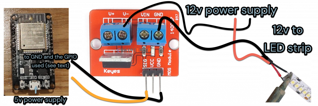
Hello, i hope you and your family are all in good health. Im trying to follow your tutorial. But the wiring diagram does not do much sense to me. I am not an electronics technician but i can follow instructions.
The drawing says GND and GPIO16, but the lines end up in VCC and SIG on the mosfet board.
Then you have V+ and Vin empty but in the photo i see you have al connectors used.
Abusing of your kindness can you elaborate on how to wire it?
thanks
I’ve corrected that now. I’m so sorry for an error in the schematic wiring diagram which now shows correctly above. The post diagrams have now been edited – thank you for alerting me Alex.
So as you correctly say, GND and GPIO16 on the ESP32 should be connected to GND and SIG on the MOSFET board.
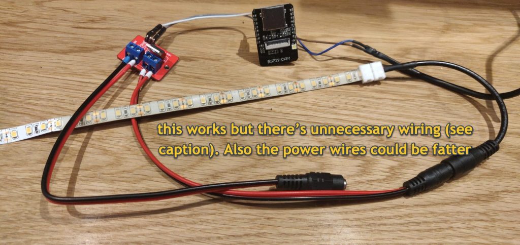
If it makes more sense (and it does) you can connect (red) V+ and Vin as the photos of my try-outs show. However to save unnecessary wiring in the ceiling, connect the red from the power supply directly to the LED strip. That’s allowed because the MOSFET dims (or switches) only the negative line.
In retrospect, the ceiling project is a long standing success. While there’s a lot of confusing wiring in the ceiling, the lights turn on dim at night and bright during the day. I might soon adjust (in Home Assistant) that to save some energy as I’m using 40W when everything is on.
Hi Roger,
Many thanks for sharing the article, it’s given me inspiration for a couple of projects. I’m no electronics expert, although I do OK hacking things together, this MOSFET though has got me stumped.
I have a USB supply powering both the esp32 and the 5v led strip being powered from pins VIN and GND from the esp32. I’ve wired it exactly as your diagram above, with the GND from the led strip connected to GND on the MOSFET, and the PSU GND connected to V- on the MOSFET. I’ve also tried switching around the GND connections. I’ve flashed the esphome code to the device and in HA I can switch the MOSFET, the red led shows on or off as expected.
however I try wiring it though, I just can’t get the led strip to come on!
As a test I followed your diagram that includes unnecessary wiring, with both + and – connected to both sides of the MOSFET. This results in the led strip being on permanently!
This is the MOSFET board I’m using https://www.amazon.co.uk/gp/product/B07F7SV84V/ref=ppx_yo_dt_b_asin_title_o02_s00?ie=UTF8&psc=1
I wondered if you had any advice as to what I may be doing wrong?
Cheers for writing in with a real conumdrum. I’m away so I have added a link which I used to get my understanding.
I’ll write more when I return
Dronebot workshop MOSFETs https://youtu.be/IG5vw6P9iY4
Hello Paul
I hope you’ve made progress. As it’s likely that you’ve wired it well I’d look first at the code (during compilation and the ESPhome log window) . Consider changing the ESP pin that you use as my board is surely different. Do see if the transition time and frequency needs changing for your setup.
The only other difference from my project is that 5v LED strip you’ve used. I hope it’s a two wire analogue strip that lights fully when given 5v. Also I assume your usb PSU can do enough amps for the number of LEDs on the strip. In the case of the ‘unnecessary wiring setup’ which will defo work I think that if I put a voltmeter on the wires going to the LED strip I’d see 5v. See if you get other readings when the light is seemingly off.
Hey Roger,
Thanks so much for the link, it’s definitely given me an understanding that I was previously lacking.
I’ve switched to a 5v 2a psu, and the led strip is 2 pin analogue, 60 leds/m, 120 total. It looks like my mis-wiring to start with actually burned the MOSFET. I was testing it last night, room was slightly darker, and I could see it turning the leds on, just very dimly.
So thanks to amazon, I had a 10x pack of MOSFETS (why buy 2 when you can get 10 for the same price eh?), I switched it out for a new one, and wham! it worked perfectly!
Just about to hook it up to the esp properly now, along with a touch switch, and hopefully drop in in to the 3d printer enclosure tonight. I’ve got a 3 day print coming up so I really need externally controlled lighting. I’ve currently got a pi4 running octoprint hooked up through a buck converter to the printer 24v psu, so should be good to power an esp and a small led strip too.
Thanks for your help with this, really appreciated, you definitely set me up on the right path 🙂
Cheers Paul. Pleased to hear this is working out and that you’re working it out by having spare bits. I think we’d agree that it’s a challenge to fix when things are broken. I have more recently been playing with WLED and 5v addressable LEDs (eg for a staircase light) and I’ve similarly broken things and been stuck. Usually the failure was due to the wrong voltage. (Octoprint is awesome so enjoy that too).
Thanks for the link Roger, that’s an excellent video for getting to grips with MOSFETs and has really helped my understanding.
It turns out with my constant messing around to try and get it working, I broke it. Thanks to a late evening working on it, it turns out the LED’s did actually come on, just really really dimly. I switched out the MOSFET for a different one and boom! worked perfectly. Well, in my test environment anyway. Just need to incorporate it into my 3d printer setup now..
Thanks for your help Roger, it’s definitely set me on the right path.
Qu1 I appreciate that it works and that most of the advice is overcautious, so I wondered how you decided on a 5v 2a PSU for 120 LEDs.
Qu2 I’m also wondering how is this LED strip used in/with your 3D printer
Yeah, I’ve got a few WLED devices around the place. It’s a nice bit of software. Funnily enough, I’ve also just built some stairway lighting, although after careful consideration I built it in esphome rather than WLED.
I’m still using as ws2812b strip, but only with a single colour. I also only wanted a single effect, a “wipe” that follows you up or down the stairs. I used a couple of VL53L0XV2 Time-of-Flight sensors, and even managed to get it to count how many people (or animals) are on the stairs. It took me a while to get the logic right, but so far it works really well. You can check out the code here
https://community.home-assistant.io/t/trying-to-increment-a-number-using-lambdas/438055/6
The ToF sensors will need some callibrating once installed, now I just need to finish the plasterboarding so I can actually install it!
Goodness me Paul, your ToF sensor has been fully off my radar so thank you so much for that. I really will investigate that sensor. eg The water shortage is affecting our supply I want to monitor the filling of water tanks with some device. What I have at present is how much power a pump uses.
Alas I need another lockdown to get my LED strip project written up. The ‘problem’ with WLED is having too much choice such than nothing is ever ‘done’.
My staircase WLED / ws2812b is a bit easy: it uses one of the microphone chips recommended by WLED Sound reactive project. The mic can sense your approach to the stairs and play a sequential light effect up the LED strip. At other times (WLED has a scheduler for different effects am/pm) each foot on the staircase triggers a light effect. WLED sends the sound trigger to other strips (eg for disco effects) and in this case pulses the strip near my desk to alert me.
Anyway, good luck and thank you for the inspiration.
I tried a few different sensors, from PIR (to many false positives), Microwave RCWL-0516’s (further research revealed some very erratic behaviour), and finally settled on the ToF. I’ve come across many posts of people using these for measuring fluid levels so could be a good option for you. Testing for my scenario has proven then to be very accurate. I’m interested to know how you get on with the project.
I agree, another lockdown could be good to give some extra time to “tidy a few things up”. I’ve (mostly) finished a few different projects recently, in my spare time, and would love to find the time to write them up and post them properly. I’ve just finished hacking together the hardware setup for a whole home voice controlled audio system. Just need to get the 3 day print started for the enclosure case now!
To answer your questions; The 2a psu was used for testing and developing. I’ve moved the ESP and the MOSFET into the printer. I’ve got an Ender 3 Max. The 24v PSU has a spare power line that I’ve tagged onto with a 3A buck converter to drop it down to a fixed 5v. This powers the pi4 with Octoprint, the ESP with the MOSFET and a touch sensor ( I may add a camera to this in the future to compliment the Pi Cam), and the LED strip. A single touch of the switch will toggle the LED strip, and a 7s touch will trigger a safe shutdown of the pi and then the smart plug that powers the whole rig. I also have a HA automation that triggers a safe shutdown of the rig if a print finishes during the night. I have the entire setup in an enclosure and the led strip is cable tied to the framework at the front, up both verticals and the top horizontal. With the inside of the enclosure being heat proof and reflective it provides a nice even distribution of light.
You WLED project is definitely intriguing. I’m guessing you need to recompile the source for the appropriate includes? Not a path I’ve ventured down, yet 🙂
I also dropped you a LinkedIn request as I thought it could be good to connect.
Hello Paul – you really are having fun there with the 3D printer – if not a Guinness record for print time!
The use of Octopi with the power plus lighting are indeed cool and useful. (Use a regular webcam, which may have a more convenient mount, on Octopi).
Your last point suggests a look at WLED Sound Reactive No compiling see link. Your need an addressable 5v LED strip and a 5v PSU, ESP32 board, and a microphone INMP441 which costs doodly.
I will of course write up my simpler version of it – simpler than Dr Zz. It’s like your MOSFET project, uses just one pin on the ESP32 so you’re pretty much there.
This blog of projects will be my aide-memoire and logbook. It’s another version of documenting code with comments.
https://github.com/atuline/WLED/wiki
Why do you indicate in the drawing that SIG must be connected to GPIO16 while you have made a connection to GPIO15 in the program code.
How does this work for you?
I’m sorry this happened – the pin numbers are pretty flexible but I should have corrected this. I have just added a new section from my still working setup to indicate that you can use any or all of several pins (eg 27,28). (It’s never a good thing to ‘hard code’ provisional pin data in a graphic). Thank you for your vigilance.
substitutions:
devicename: ceilingled
# use below as ${devicename} xyz
output:
# LED pins doing PWM
– platform: ledc
pin: GPIO27
frequency: 20000Hz
id: ledcout27
– platform: ledc
pin: GPIO26
frequency: 20000Hz
id: ledcout26
– platform: ledc
pin: GPIO25
frequency: 20000Hz
id: ledcout25
– platform: ledc
pin: GPIO33
frequency: 20000Hz
id: ledcout33
# – platform: gpio
# pin: GPIO27
# id: ledcout27
# light
light:
– platform: monochromatic
output: ledcout27
name: ${devicename}27 light12s
default_transition_length: 4s
– platform: monochromatic
output: ledcout26
name: ${devicename}26 light12s
default_transition_length: 4s
– platform: monochromatic
output: ledcout25
name: ${devicename}25 light12s
default_transition_length: 4s
– platform: monochromatic
output: ledcout33
name: ${devicename}33 light12s
default_transition_length: 4s
Thank you very much Roger for the extensive information.
I’m going to build the circuit this week.
Greetings from Belgium.
Fred
Thank you too. All best